Verifying the Integrity of Your Shipment
CAUTION! Thales employs a number of security measures to allow you to verify that your new hardware was not intercepted in transit or otherwise tampered with before you received it. To verify the authenticity and handling history of your received items, review the following checklist before you unpack your new hardware, and then follow the checklist as you unpack each item.
CAUTION! Before you start, see Critical HSM Card-Handling below.
| Step | Yes | No |
|---|---|---|
|
1.Do the items received (individual items, part numbers) match those listed in the enclosed packing list? If yes, go to the next step. If no, contact Thales support. |
||
|
2.Before you received the product, did you receive an advanced shipping notification providing details regarding the shipment (part numbers and serial numbers for the product, and for tamper-evident bag(s))? If yes, go to the next step. If no, contact Thales support. |
||
|
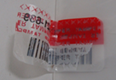
3.Are any tamper-evident bag serial numbers that are listed in the advanced shipping notification present, and do they match the actual bag(s) received? The tamper-evident bag serial numbers appear as shown below.
If yes, go to the next step. If no, contact Thales support. NOTE The serial number of the bag is tracked. Serial numbers of additional stickers on the bag are not tracked, and are meant only for inspection against physical alteration. |
||
|
4.Did you receive any tamper-evident bags that are not listed on the advance shipping notification? If yes, contact Thales support. If no, go to the next step. |
||
|
5.
If no, contact Thales support. If yes, go to the next step. NOTE The serial number of the bag is tracked. Serial numbers of additional stickers on the bag are not tracked, and are meant only for inspection against physical alteration. |
||
|
6.Are there any signs of physical tampering?
If yes, contact Thales support. If no, go to the next step. |
||
|
7.Once you have verified all of the received items, you can proceed with the installation. |


Critical HSM Card-Handling
The Thales Luna PCIe HSM 7 features 2 input headers:
>Decommission Input Header
>Chassis Open Tamper Input Header
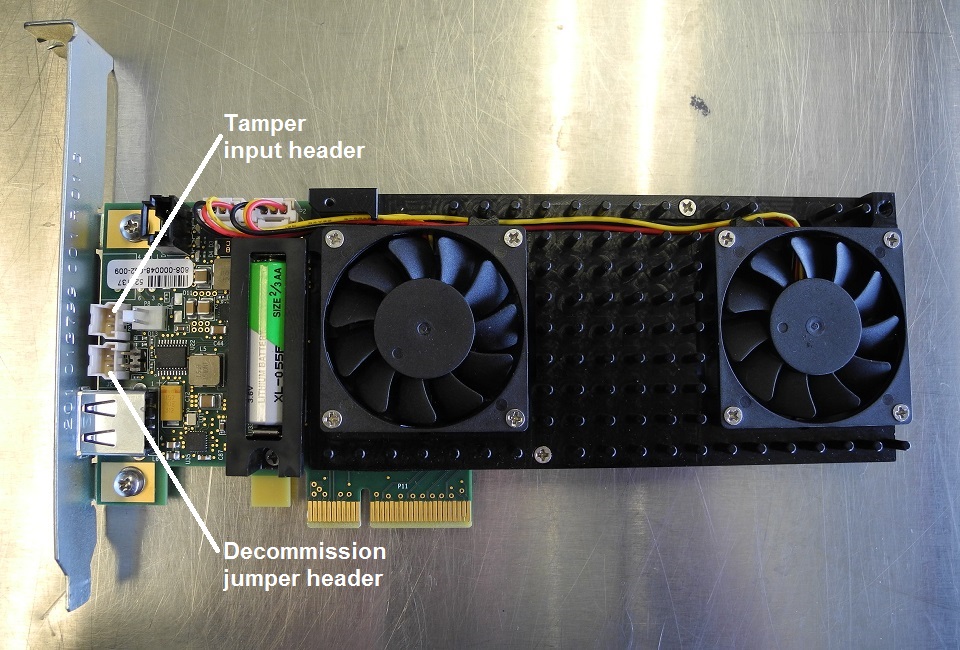
These headers can optionally be connected to normally-open external switches to trigger an HSM decommission event or a chassis-open tamper event.
Unintended Decommission and Chassis open tamper events can occur because of the following:
>Improper handling, resulting in a negative electrostatic discharge (ESD) to these input header pins on the front and back of the HSM card.
>Improper handling, resulting in inadvertent shorting of these input header pins on the front or back of the HSM card.
>Loose or faulty external switch wiring, shorting these header pin inputs
The following section identifies imperative precautions to prevent false triggers due to ESD.
Preventative Recommendations:
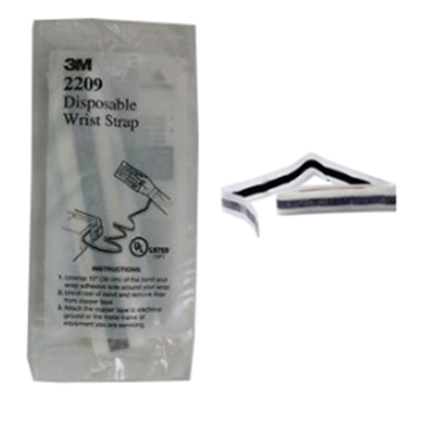
Anyone handling the Luna PCIe HSM 7 should always wear the ESD wrist strap provided, and ensure that the strap is properly connected to an earth ground.
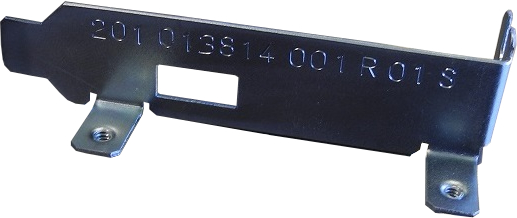
The Luna PCIe HSM 7 card should be handled very carefully and only by the metal card bracket or edges of the card.
It is very important to avoid contact on both sides of the PCIe HSM near the area around the decommission and chassis open tamper input headers.
When the Luna PCIe HSM 7 .card is unpacked from its anti-static shipping envelope, and is outside a server chassis:
>Never place the HSM card on any conductive surface such as a server chassis or power supply enclosure, that can cause shorting.
>Always place the HSM card on an ESD dissipative surface. An earth grounded ESD bench-top mat, in good condition, is strongly recommended.
>The use of air ionizing fans in the immediate work area is recommended. Ionizing fans should be positioned to ensure that ionized air flows across the workbench and over the entire card.
If the Luna PCIe HSM 7 is handled with gloves, only ESD dissipative gloves should be used. Examples are pictured.
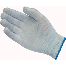
Glove, Knit Nylon Carbon Fiber ESD Dissipative
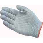
Glove, Knit Nylon Carbon Fiber ESD Dissipative, with PVC Dot Grip
If the decommission input header is not used, we strongly recommend that you disable decommissioning by setting HSM Policy 46 Disable Decommission (to 1).
This instructs the HSM to disregard hardware decommission signals entirely, and eliminates the possibility of unintended decommissions due to handing-related ESD or other factors.
NOTE Policy 46 is destructive, as a result it is not easily reversible. Ensure that you have backups of any important keys and crypto objects.
There is no equivalent policy to disable the chassis open tamper input.
Protective / Preventive Plug for Decommission and Tamper Headers
Starting in 2026 the exposed ends of the Decommission and Tamper header pins on the reverse side of the Luna PCIe HSM 7 HSM card are covered with RTV silicone. The working ends of the pins (within the header shrouds on the obverse side) receive protective plugs. These measures help to prevent accidental shorting across the pins or exposure to electrostatic discharge (ESD)
>during installation handling, or
>while working on other components and connections within your host machine.
In the event that you need to remove one of the protective plugs, such as when installing a connection from a sensor or switch, we recommend tweezers or very slim needle-nose pliers.
The protective plug is an unpopulated Molex Sherlock 2mm connector housing (no conductors installed). It is held in place by a latch that engages a small tab on the shroud of the header. The interior of the plug has two channels corresponding to the header pins. Those channels are separated by a divider to keep the header pins physically and electrically isolated from each other.

To remove the protective plug from the Decommission header or the Tamper header.
1.Grasp the plug securely from above with your tweezers or pliers. One arm or point of the tool goes on the outside of the plug, against the upper portion of the latch, while the other point goes inside one of the vertical holes (with a pin in it).
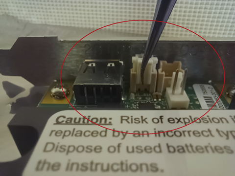
NOTE As long as you and your tool and the HSM card share a dissipative connection (the card is on an anti-static mat and you are wearing an antistatic strap connected to the mat), it is safe for a single arm of the tool to touch one pin of the current header.
2.Pinch the plug near the top of its latch, causing the lower portion of the latch to spring outward, disengaging from the tab on the shroud.
3.Maintaining the grip, pull upward to remove the plug from the header.
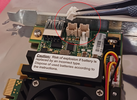
NOTE The Decommission header is chosen for illustration only because it is in a more visible position than the Tamper header. The procedure is the same for either header and plug.
4.To reinsert the plug, reverse the steps above.
NOTE When you receive a new Luna Network HSM 7, you will see log entries recorded before the unit was shipped. These include two login attempts that are part of the factory test process to ensure that the password was reset prior to shipment, plus entries related to NTLS testing, certificate configuration, and license verification. Most of these are for assurance of the appliance surrounding the cryptographic module (the HSM), and all of this is to be expected and does not indicate device tampering. Clearing such artifacts would require re-logging in, which would generate more log entries, to no gain.
Secure Transport Mode is used to reassure against tampering of the embedded cryptographic module in transit; launching STM on the HSM (module) requires login to the appliance. This is done before the final appliance-level steps mentioned above. The HSM component must then remain untouched between the time STM is activated and the time you receive, confirm, and deactivate.