Installing the SafeNet Luna Network HSM Hardware
This section provides basic SafeNet Luna Network HSM hardware installation instructions (connecting cables, booting, etc.). If you intend to mount the appliance in a standard equipment rack, see Rack-Mounting the SafeNet Luna Network HSM before following these instructions.
Installation Notes
>Any computer that is to act as a client to the SafeNet Luna Network HSM appliance must have the Client software installed. Windows users should log in to their computer as a user with Administrator privileges.
>A computer that is to be used only for administering the SafeNet Luna Network HSM does not need the Client software – only an SSH client such as the provided PuTTY program for Windows, or the SSH utilities that come standard with most Linux and UNIX platforms.
>A computer that is to be used for Remote PED workstation operation against a SafeNet Luna Network HSM must have the PEDServer software and PED USB driver installed. Applies to select Windows platforms only.
>All three tasks (Client, administration, and Remote PED) can be performed on a single computer, but in normal practice they are often separate tasks for separate computers.
>See About Remote PED if you will be using Remote PED.
Installing the SafeNet Luna Network HSM Hardware
Follow these instructions to install and begin configuring the appliance.
To install the SafeNet Luna Network HSM hardware
1.Insert the power (a) and network (b) cables at the rear panel.
For proper redundancy and best reliability, the power cables should connect to two completely independent power sources.

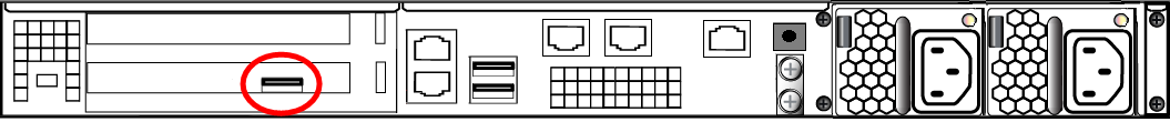
2.If you have a PED-authenticated SafeNet Luna Network HSM, connect the PED directly to the HSM card's USB port (on the rear panel's left side), using the included USB-to-MiniUSB PED cable. See also Local PED Setup. If you have a password-authenticated HSM, skip to the next step.
NOTE Refreshed-hardware PEDs - identifiable by the part number on the manufacturer's label: 808-000060-002 or 808-000060-003, or by firmware 2.8.0 or later - is powered by the USB connection and does not require a separate, external AC power adapter.
If you have an older PED, the PED must be connected to a suitable power source. The USB 2.0 connection does not provide enough power to run the PED.
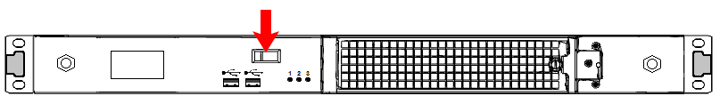
3.Press and release the Start/Stop switch on the front panel.
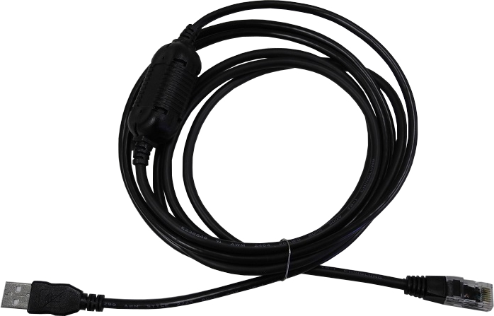
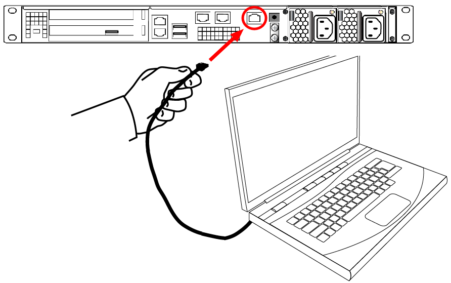
4.Connect the terminal port on the HSM appliance's rear panel to a dumb terminal, PC, or laptop, using the USB-to-RJ45 adapter cable (supplied). This terminal provides serial access to LunaSH for initial network configuration. See Opening a Serial Connection for more information.
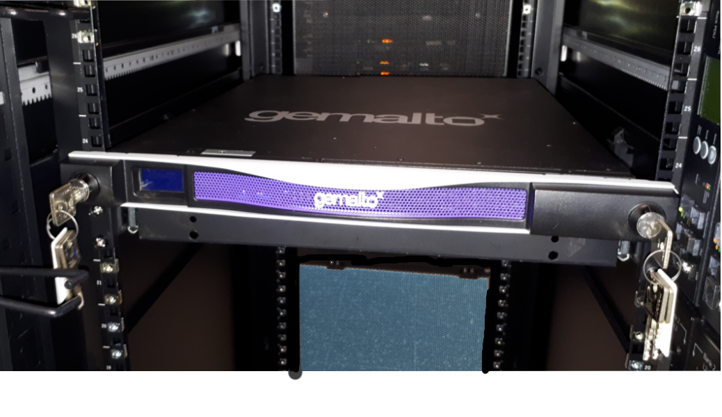
5.For maximum physical access security, when you are finished configuring the HSM, fit the locking bezel over the HSM's faceplate. Certain security standards require the use of these physical access measures. The locks fit over the posts highlighted below.
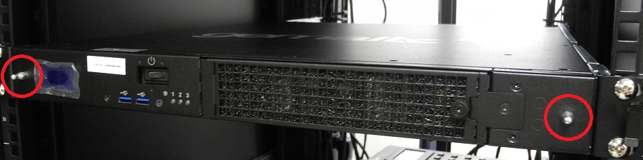
Turn the keys to the vertical position to lock the bezel. The keys cannot be removed if the bezel is unlocked. The two locks are keyed differently, so the keys can be issued to different security personnel and kept in secure, separate locations.
NOTE Leaving the keys in the bezel could interfere with closing the rack door, and compromise security.
Installing optional 10 Gigabit Optical Ethernet
If you ordered the 10G Optical Ethernet option, then the two side-by-side RJ45 ports are replaced by optical-ready SFP+ connectors. The SFP optical Ethernet modules are packed separately, within the Network HSM shipping carton.
The original SafeNet Luna Network HSM, with copper-only 1G Ethernet, looks like this (below) at the back panel.

The SafeNet Luna Network HSM with the 10G Optical Ethernet option looks like this, below. The two optical-ready connectors are protected by dust covers during shipping and handling.
NOTE The physical ports assigned Ethernet port numbers by system software are changed; the new optical ports become Eth0 and Eth1, while the remaining RJ45 1G copper ports are labeled Eth2 and Eth3. This could require change to setup scripting, if you have previously installed and configured Network HSM appliances with copper-only Ethernet ports.

To install the SFP modules
1.Locate the SFP modules in the accessory box, within the Network HSM shipping carton.
2.Remove the dust plug from one of the two SFP+ connectors on the back panel of the Network HSM.
3.Remove an SFP module from its packaging and slide it into the selected connector slot, ensuring that the module seats firmly, making a positive connection at the back of the slot.

4.Repeat for the other 10G module if desired.
To connect a Dual L-to-L optical cable to an installed 10G SFP module
1.Remove the dust plug from the installed 10G SFP Ethernet module.
2.Insert the dual cable connector as shown.
